Tutorial: Lobar analysis of CT data#
Introduction#
This tutorial will describe the completed process for obtaining lobar analysis results using the Pulmonary Toolkit. Some stages (such as loading and visualisation) and covered in more detail in previous tutorials, so refer to these if you are unclear on certain concepts.
Loading the dataset#
Click the Patients button to open the Patient Browser. To import a new dataset, click the + button. Then select the folder or folders containing the data to import. Importing data may take a few minutes. Once your dataset has been imported, it will appear in the Patient Browser. The right side of the Patient Browser shows every dataset (series) you have available, grouped by patient. Use the scrollbar or the mousewheel to move through the patients. The left panel is a shortcut list which allows you to scroll straight to a particular patient.
Click on a dataset (image series) to load that series into the PTK. If this is the first time you have visualised this series, the PTK will automatically perform some initial operations such as detecting the lung region of interest. This may take a few minutes.
# Segmenting the lobes # On the right of the main PTK screen there are a number of ‘tabs’ (File, Segment, View, etc.). Click Segment to select the Segmentation panel.
Then click Lobes to perform lobe segmentation. This may take 5–10 minutes if this is the first time you have run lobe segmentation for this dataset.
Verifying the lobe segmentation#
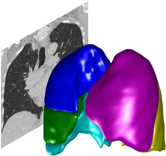
After the lobe segmentation completes, the segmentation will appear as a colour overlay on the main lung image. Verifying the lobe segmentation It is important you always verify the automated lobe segmentation for every dataset you analyse. You may need to correct the lobar boundaries, depending on the level of accuracy you require. You only need to perform verification and correction once for each dataset; the PTK will remember your corrections for future use. After the lobe segmentation completes, the segmentation will appear as a colour overlay on the main lung image, as shown above. Verify the lobar boundaries are correct by scrolling through the image slices (use the mouse wheel or scrollbar at the side of the image). You can switch orientation, zoom and pan as required. If you don’t know how to do this, go back to the earlier tutorials and familiarise yourself with navigating the image in the PTK. You may also wish to adjust the overlay opacity (the opacity is set by the slider to the right of Opacity – slide it to the right to make the segmentation overlay more opaque). If you don’t see the colour overlay, make sure you have the ‘Overlay’ checkbox selected (underneath the image window), and make sure the overlay opacity is set high enough to be visible.
Correcting the outer lung boundaries#
Normally, you won’t need to correct the outer boundaries of the lung segmentation, so you can skip straight on to correcting the boundaries between the lobes in the next section. However, if you do need to correct the outer boundaries of the lungs, the procedure is similar to the lobar boundary correction described below. Click Left and Right Lungs to load the lung segmentation, then choose the Correct tab (as described below) and follow the instructions below, except now you are clicking to modify the outer boundaries of the lung. You should make any corrections to the lung boundaries before making corrections to the lobar boundaries.
## Correcting the lobar boundaries ##
After you run the lobe segmentation by selecting Lobes above, a new Correct tab appears. If you need to correct the boundaries between lobes, select this Correct tab and the PTK will enter manual correction mode.
When you enter manual correct mode, a new “Edit” tool is selected. Use This appears as a hand icon. Use the edit tool to make small adjustments to the fissure boundaries between the lobes. To do this, click the finger of the hand on the fissure point where you want the boundary to be. The boundary will be shifted towards that point (in 3D). Note, this may take a second or two. Click the finger on the new boundary point The boundary shifts to this point in 3D You may need to click a number of times on different slices to get the boundary where you want it to be. The PTK tries to ensure the boundary is smooth and continuous in 3D; this means it will not always do precisely what you want, but it will ensure the boundary is more realistic. If you are trying to make a boundary connect to the edge of the lung, try clicking just off the edge of the image, near where you want the boundary to touch the edge of the lungs. You can press U (for undo) one or more times to undo the last few edits. While in Edit mode you can still switch image orientation, cine through the slices using the mouse wheel or the scrollbar, pan using SHIFT+drag, and zoom using CTRL+drag. You can switch to a different tool (eg W/L, Cine etc.) but this will switch away from the Edit tool, and you will have to switch back to the Edit tool in order to continue correcting the boundaries. To switch back to the edit tool, click the Edit button below the image. When you have finished your editing, click the Save button in the Correct tab. The corrections will be saved internally (you don’t need to enter a filename) and your corrected lobar boundaries will be used for all future anlaysis. If you don’t click Save, you will be asked whether you want to save when you leave correction mode.
Removing manual corrections#
When in correction mode, the Delete all editing button will erase all of your edits for the lobe segmentation for this dataset, and revert back to the automatically generated segmentation.
Using an external editor#
As an alternative to using the PTK’s correct tools, you can edit the segmentations using an external editor. You can use the Export edit button to save the lobe segmentation in a suitable format (such as raw/mhd), load up the edit in a 3D editor, make the appropriate corrections, and then import the edited image back into PTK using the Import Edit button. See the appendix for a step-by-step example of how to do this using ITK-Snap. If you use the Import Edit facility, be very careful not to accidentally load in the wrong segmentation from a different dataset. Always verify any segmentation you import looks OK after importing. Be aware that unlike the PTK, many external editing tools are 2D and will not guarantee connectivity and smoothness of the lobar boundaries between adjacent slices. As a result, if you manually draw lobar boundaries in one orientation (e.g. on axial slices), they may look odd when viewed in a different orientation (e.g. coronal slices). The PTK’s internal correction tools operate in 3D and do not suffer from this problem
Performing lobar analysis#
Once you have verified and corrected the lobar boundaries, you can run automated lobar analysis to generate lobar measurements such as emphysema percentage and mean tissue density. Click the Analyse tab Click Density Metrics to run CT density-based analysis across the lungs and lobes
When the analysis completes, the results will be written to a csv file (a comma-separated text file which can be opened in Excel or any text editor. This is saved to a Density Metrics folder which is a subfolder of the Output folder for this dataset. The folder will open automatically on PC and Mac.
For Linux systems, you may have to open the output folder yourself. In this case the Open the results folder button will print the full folder path.
## Axial, Coronal and Sagittal analysis ## Analysis can also be performed by slicing the lung into thick slabs in any one of the three orientations (coronal, sagittal, axial) and performing mean measurements over each slab. Example of lung divided into thick axial slices. To perform this kind of slice analysis, choose the Axial, Coronal or Sagittal metrics button in the analyse tab. The analysis will be performed and written out to the output folder. For slice-based analysis, measurements are performed in each slice. An additional measurement is written out, which identifies each slice (the distance of the slice along the axis). A separate file is produced for each lung region (the whole of the lung, the individual left and right lungs, and each of the lobes). For example, one file will show the analysis from dividing the left lung into slices, and another the right lung. If you are only interested in the whole lung divided into slices then you can ignore the other regions. The locations of the slices are the same for all files.
## Appendix: Editing a lung or lobe segmentation with an external editor (ITK-Snap) ## This appendix describes how to perform manual editing of the lung or lobar boundaries using an external editor - in this case ITK-Snap. Be aware that editing a 3D segmentation in a 2D editor may not produce good results. The PTK’s correction tools are 3-dimensional so that any changes are smoothed across adjacent slices. In general using the PTK’s tools will produce better results than trying to manually edit each slice in an external editor. However, sometimes you may need to use an external editor to deal with problematic datasets. To work with ITK-Snap you will need to save out two files: You may need to save out the scanner image file into a format that ITK can read, for example a 16-bit metaheader and raw file (mhd/raw). To do this from PTK, select the File tab, the Save Image button and choose 16-bit mhd/raw. Save out the current segmentation (the lungs or the lobes depending on what you want to correct). For example, for the lobes, first choose Lobes from the Segment tab, then Export Edit from the Correct tab. For the segmentation, you can choose an 8-bit metaheader and raw file Assuming you have installed ITK-Snap, now start it up. From the File menu, Open Greyscale Image and choose your saved image file. You may need to play with the image contrast (Tools / Image Contrast) to make the image clear. From the Segmentation menu, Load From Image and select your saved segmentation file. You should now see your image and the segmented lobes transparent overlay on top. Now If you wish, make your preferred view full-screen (click the + button next to the right of your preferred view). Select the Paintbrush tool (shortcut: key 5) Change the Shape to Round, and change the Size to your desired size. You can modify the size using the + and - shortcut keys. Choose the Active drawing label to set the segmentation colour, which defines the lobe, or none to set the background. The colours you need to set for PTK are 1: upper right lobe; 2: middle right lobe; 4: lower right lobe; 5: lower left lobe; 6: upper left lobe. If you are modifying a lung segmentation, 1 is the right lung and 2 is the left lung. Use the Paintbrush or other tools to modify the segmentation, remembering you can move between slices using the mouse scroll wheel or page up/page down. Once you have made your changes, Save As Image from the Segmentation menu, and choose an 8-bit metaheader file. Load your new segmentation into PTK using the Import Edit from the Correct tab.