How to perform and correct lobe Segmentations#
The automated lobe segmentation is based on the method published here:
Doel et al, Pulmonary lobe segmentation from CT images using fissureness, airways, vessels and multilevel B-splines (2012)
The algorithm is fully automated; however there are certain steps which, may produce inaccurate results depending on your datasets. To fix this, there are manual verification and correction tools which you can perform at each step. With some help from the manual correction tools you can usually produce good lobe segmentations for most datasets.
The steps of the method are as follows:
Segment the airways -
SEGMENT REGION/Airwaysbutton on the gui (plugin code:PTKAirways.m)
to visualise the results of the airway segmentaiton step, click
Airwayson the GUI. The BLUE voxels are the segmented airways.
Label the airways according to which pulmonary segment they serve -
SEGMENT REGION/Lobal bronchi(plugin code:PTKAirwaysLabelledByLobe)
To visualise the results of airway labelling, click
Lobar Bronchion the GUI. The segmented airways are coloured by broncus.WARNING: the automatic airway labelling algorithm is not completely robust. It may incorrectly label some of the airways, which will lead to errors in the final lobe segmentation. Hence the following inspection and correct step is required to ensure correct lobr segmentation
MANUAL STEP: inspect the airway labelling and correct if necessary
Visualise the airway labelling by selecting
Lobar Bronchion the GUI. Each bronchus is assigned a label (colour) coloured according to the lobe it serves.Blue (RIGHT UPPER LOBE)
Green (RIGHT MIDDLE LOBE)
Cyan (RIGHT LOWER LOBE)
Magenta (LEFT UPPER LOBE)
Yellow (LEFT LOWER LOBE)
Red - the algorithm is uncertain (you can assign a lobe to improve results)
Grey - the airway serves more than one lobe
If any bronchus is incorrectly coloured, you will need to modify the labels
Select the
Correcttab to edit the labelsFind an incorrectly labelled airway, right-click and choose the correct label
When you change the label on a bronchus, the child bronchi will automatically be assigned that same label
Segment the left and right lungs -
SEGMENT REGION/Lungsbutton on the gui (plugin code:PTKLeftAndRightLungs.m)MANUAL STEP: inspect the outer boudaries of the left and right lungs and correct if necessary
Visualise the lung segmentation by selecting
Lungson the GUI. Each lung is assigned a label (colour)Blue (RIGHT LUNG)
Green (LEFT LUNG)
You can make corrections on the outer lung boundaries, or the boudaries between lungs (if they are touching)
Select the
Correcttab to edit the lung boudariesUse the
Edit Boundarytool to click on a new outer boudary point, shifting the whole boundary in 3D towards that pointUse the
Painttool to paint a whole 3D sphere in a lung colour
Once you manually edit a lung boundary, your manual segmentation will override all automated results for the lung segmentation. If you want to return to automated results you will need to delete all your corrections by clicking
Delete edits
Compute vesselness density (plugin code:
PTKVesselDensity.m)Compute approximate lobe segmentaiton (plugin code:
PTKLobesByVesselnessDensityUsingWatershed)
this uses the labelled airways to seed a watershed transform based on the vesselness density
The results of this are usually reasonably close to the true fissure. If they are very poor, it is often due to an incorrect airway labelling (see above step to manually correct airway labelling)
You can see the result of this approximation by enabling
Developer modeand selectingLobes/Lobes Initial Guessunder thePluginstab
Compute fissureness based on Hessian transform (plugin code:
PTKFissureness.m)Iteratively compute improved fissures (plugin code:
PTKFissurenPlane.m)
These are computed by fitting points of high fissureness which lie in a region close to the previously computed approximate lobar boundaries, and smoothing the result using a multilevel B-spline
Segment lobes using the new fissure plans -
SEGMENT REGION/Lobesbutton on the gui (plugin code:PTKLobes.m)MANUAL STEP: inspect the boundaries between lobes and correct if necessary
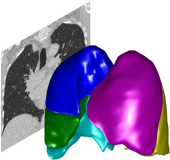
Visualise the lobe segmentation by selecting
Lobeson the GUI. Each lobe is assigned a label (colour)Blue (RIGHT UPPER LOBE)
Green (RIGHT MIDDLE LOBE)
Cyan (RIGHT LOWER LOBE)
Magenta (LEFT UPPER LOBE)
Yellow (LEFT LOWER LOBE)
If the boundaries are highly inaccurate, you should check the airway labelling above and correct that before continuing to this step.
You can make small corrections on the boundaries between lobes
Select the
Correcttab to edit the lobar boudariesUse the
Edit Boundarytool to click on a new boudary point, shifting the whole boundary in 3D towards that pointUse the
Painttool to paint a whole 3D sphere in a lobar colour
Once you manually edit a lobar boundary, your manual segmentation will override all automated results. If you want to return to automated results you will need to delete all your corrections by clicking
Delete edits